The diyaudio store has again SilentSwitchers in stock.
Update Jan 2023: There are no more SilentSwitchers available, and no plans for a new batch.
Update 14 August 2018: The MKII version now has the option to set the 'analog' output voltages to your own requirements. As-delivered they are set at +/-15V, but by soldering a set of 4 resistors to the board you can set the output to +/-12V, +/-8V or +/-5V (or a combination). Custorm values are possible, contact me for resistor values. See the new User Guide for detailed info.
Note also that the PCB has the same form factor and the same size. Get them at the diyaudio store
Update 7 September 2017: I have no more stock of SilentSwitchers available, but the diyaudio.com store has some stock. These are exactly the same as mine - there's only one type. You can order from them online.
Update 21 July 2017: I am going to design a version where you can change the output voltage by changing 4 size 1206 SMD resistors. The idea is to also change the primary switcher output to keep dissipation and efficiency under control. So a total of 4 resistors have to be changed.
A friend of mine is going to put together a few prototypes from +/-5V to +/-24V so I can do some measurements.
Specials: Unfortunately I can no longer offer a special on a Quad SilentSwitchers as I found out I am actually losing money on those (thank you IRS...). So you can get Singles at € 69 or a Dual (which is a pair of Singles) for € 129. Shipping is € 6 any order size, anywhere, with tracking.
Low voltage output selection: In the video and earlier documentaion I mentioned that if you remove the jumper for the low voltage selection, the low voltage output is 6V. I have changed that to 6.5V to give you extra headroom for local regulation down to 5V or 3.3V. So the low voltage output selections are: 6.5V/5V/3.3V
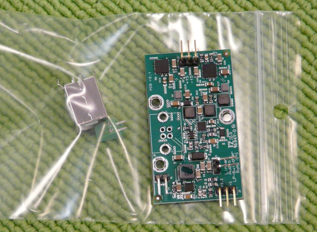
Connection headers: all connection headers for output and on/off switch are now 90 degr. angled headers to keep the profile of the mounted and connected unit as low as possible. There are still two input connectors delivered with each unit, a USB connector and a 2-pin screw connector.
FAQ: Some questions came up from people working on implementing a SilentSwitcher in their project. I will collect these (and the replies) in a FAQ that can be downloaded here.
Shipment tracking: Normally when I ship your SilentSwitchers I will forward the tracking # to you. You can track your shipment (English language) through the German Post/DHL. Just enter the tracking number I emailed to you. For US destinations, when the shipment has entered US national territory you can track it there as well.
update: I have a video about the SilentSwitcher now!
update: Our friend Ergo Esken created a few CAD drawings showing the exact mounting hole positions and dimensions for the SilentSwitcher. You can download them here. Many thanks again to Ergo to do this!
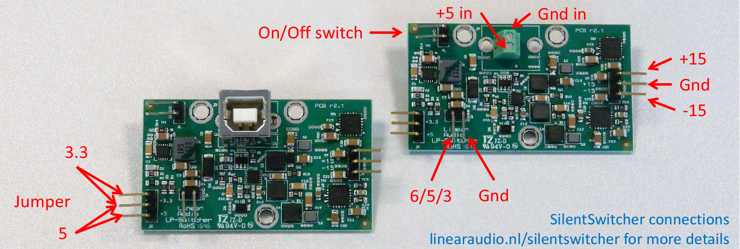 update: this is the connection diagram which will be included in each shipment.
Introduction
It had to happen one day. I realised that my equipment was steadily getting smaller and the power supply with it's transformer and rectifier and reservoir caps remained as large and looming as before. I had been looking at switched-mode power supplies before but was never quite satisfied with the performance of the units you can buy off the shelf. They just don't worry about audio circuits the way we do! So the only remaining option was to do-it-myself.
I spend a few weeks studying the state of the art in switchers and realised that the situation is radically different from what I thought is was. The reason: the very high requirements for tablets and smart phones have driven switcher technology to increadible quality jumps ahead. Not ony that, but linear (post) regulator performance has leapfrogged those old audio standby's (LM137/337 anyone) as well. For example, the Texas TPS7A47 linear regulator has a broadband output noise of just 4.7uV. That's micro-volts. Very, very hard to beat, even with a Superreg.
The concept
 Overwhelmingly, analog circuitry wants to be fed with +/-15VDC, so that was the target for my adventure. But increasingly the analog is combined with something digital, a DAC, a microcontroller, LEDs, relays, etcetera. So it would be nice to also include a supply for that. Long story short: the SilentSwitcher outputs +/-15VDC at up to 150mA each, as well as a separate supply that can be jumper-selected for 6V, 5V or 3.3. At a minimum of 0.5A. (See below for higher current options). The 6V option is provided in case you want to down-regulate locally to 5V or 3.3V.
The +/-15V linear regulators are fed by a dual switcher, working at a high frequency, so as to minimize radiated and conducted noise. Until recently this would not have been an option, but the linear post-regulators I selected have a PSRR of over 60dB at more than 1MHz! Absolutely incredible and exacty what is needed to clench what little ripple remains from the switcher. The 6/5/3.3 V source uses another dedicated high-frequeny switcher. It works in constant current mode into a relatively high decoupling cap and has low residual ripple.
I also put a lot of effort in designing the PCB to avoid excess radiation; very low impedance ground- and current paths, short traces, decoupling caps right at the source, etcetera, etcetera. More time went into that than into the circuit itself.
Connectivity
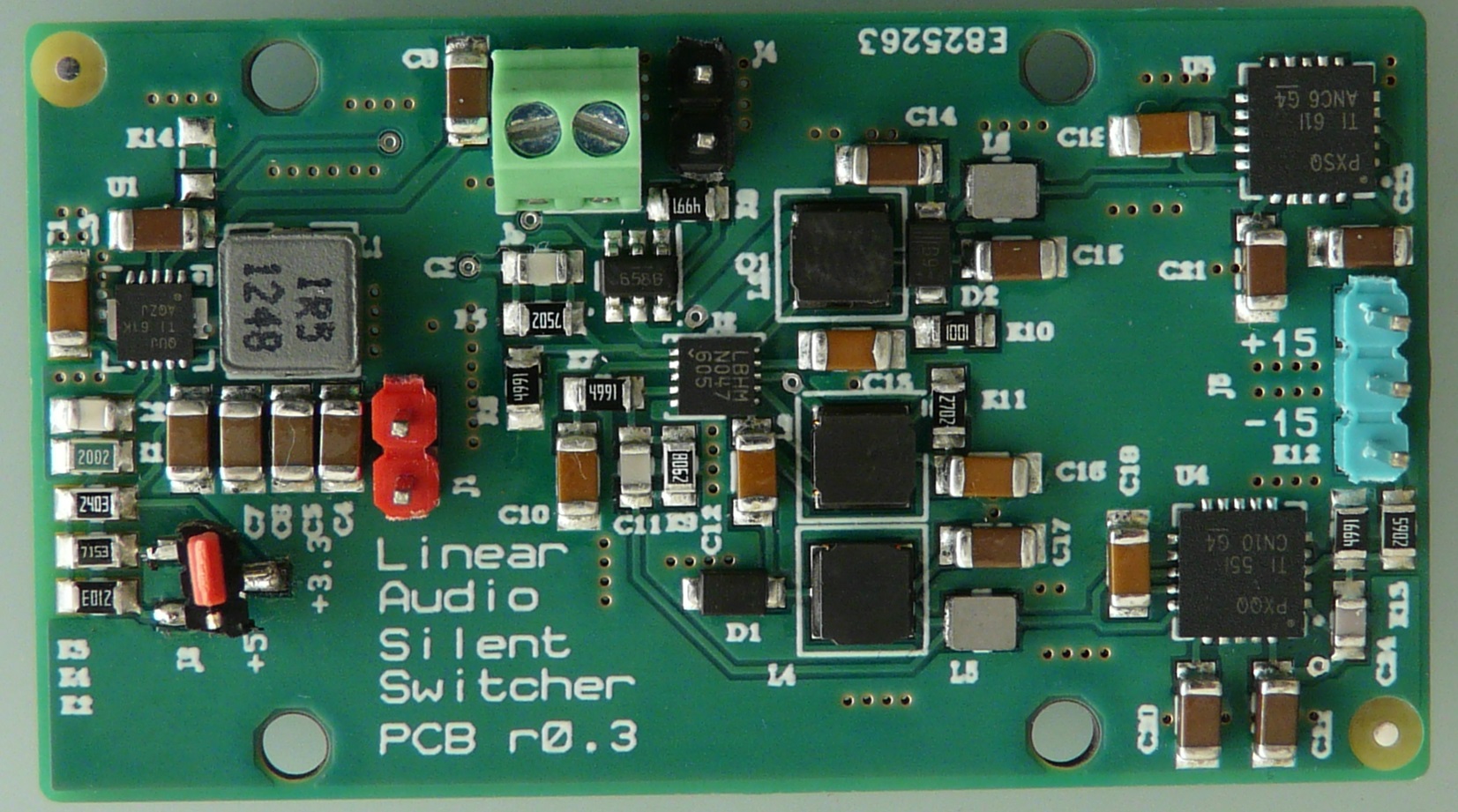
There are 2- and 3-pin headers on the PCB to connect the load, and a 2-pin header for an On/Off switch. The connection to the 5V source can be done in two ways: you can fit a small 2-pin screw-terminal block, or you can fit a straight-up B-type USB connector. Be sure to mount the USB connector on the same board side as the parts and the headers! The USB connector provides a nice option to mount the SilentSwitcher on the back panel of an enclosure with a hole cut out for the USB connector; no further input wiring is necessary and everything is very compact and clean. (The pic below shows the screw-terminal version).
What does it for me?
Almost any small signal audio project will benefit from a SilentSwitcher. A RIAA phono preamp; a line preamp with or without tone controls, an active filter, buffers, cross-overs. Electronic volume controls, headphone amps; anything that has opamps it in.Opamp and discrete audio circuits almost always run at +/-15V, and even if the are designed for say +/-12V or +/-16V, they will almost always run fine at +/-15V. At 150mA (or more, see below at powering options) it's enough for all but the most power hungry circuits.
The 6/5/3.3V output would be ideal for a DAC or streamer with a dedicated controller. The 0.5A current (up to 1A with extra power option, see below) goes a long way to power a dedicated unit with a display, some relays, LEDs, etc. SilentSwitcher is a very high performance turnkey power supply for such mixed systems.
Supplying the supply
As noted, the SilentSwitcher can run from a standard 5V USB charger. In my use for the Autoranger, I have it connected to a PowerBank (PB) which is in turn connected to a USB charger. When I want to use the Autoranger completely separated from the mains I just unplug the charger and let it run on the PB. You can already get PBs of say 4000mA-Hrs for fifteen bucks, so that's a very good option.
But you can also run it from a wallwart or (LiPo) batteries, anything between 3V and 10V will do.
The start-up of the various parts of the SilentSwitcher is timed such that the inrush current doesn't get above 2A or so, even at max load.
The current limits (150mA at the +/-15V and 0.5A at the 6/5/3.3V simultaneously) are such that they can be used with a standard 5V/2.1A USB charger. However, if you use for instance batteries or a wallwart delivering 9V at 2A, the available output currents are doubled.
Some measurements (with many thanks to Jack Walton aka jackinnj)
Standard measurements on regulated power supplies include output noise versus frequency, and output impedance versus frequency. You'd want both to be as low as possible. Jack has a lot of experience (and the instrumentation!) for doing this type of measurement (see also his article in Linear Audio Vol 4). Here are some measurements on the SilentSwitcher. Very, very respectable for a switching power supplies. Chances are that the 'linear' power supply in your unit is much worse.
Also, see the eye-opening demo by John Siau, Benchmarks' chief designer about how much better switchers can potentially get compared to the old and tired transformer/rectifier/bottle cap (fun part starts at just before 8 minutes). 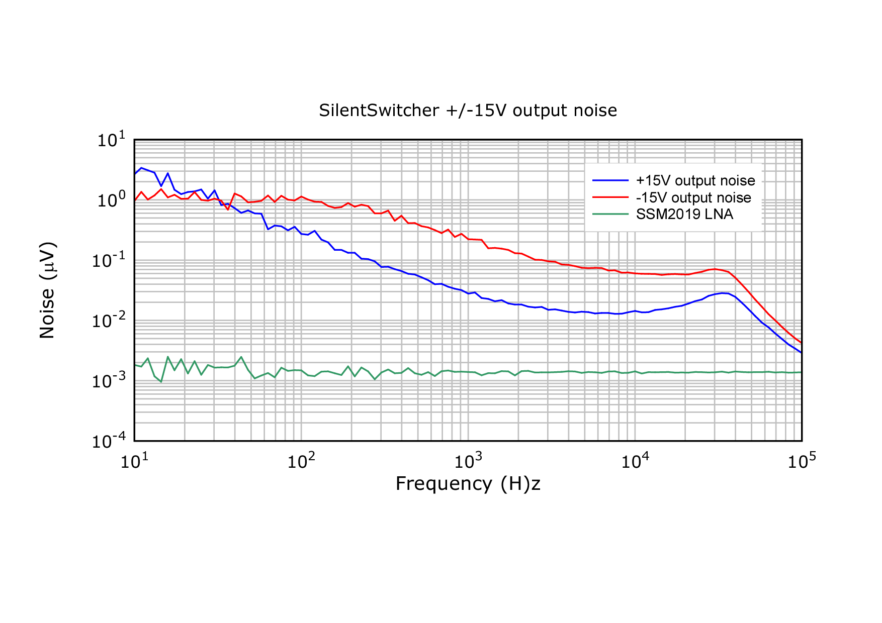
The +/-15V outputs of the linear post-regulators have 0.2uV (neg) and 0.02uV (pos) noise at 1kHz, and broadband audio band noise level of less than 40uV (neg) and 7.5uV (pos). That is impressive by any standard. (The baseline for the test amplifier is also shown).
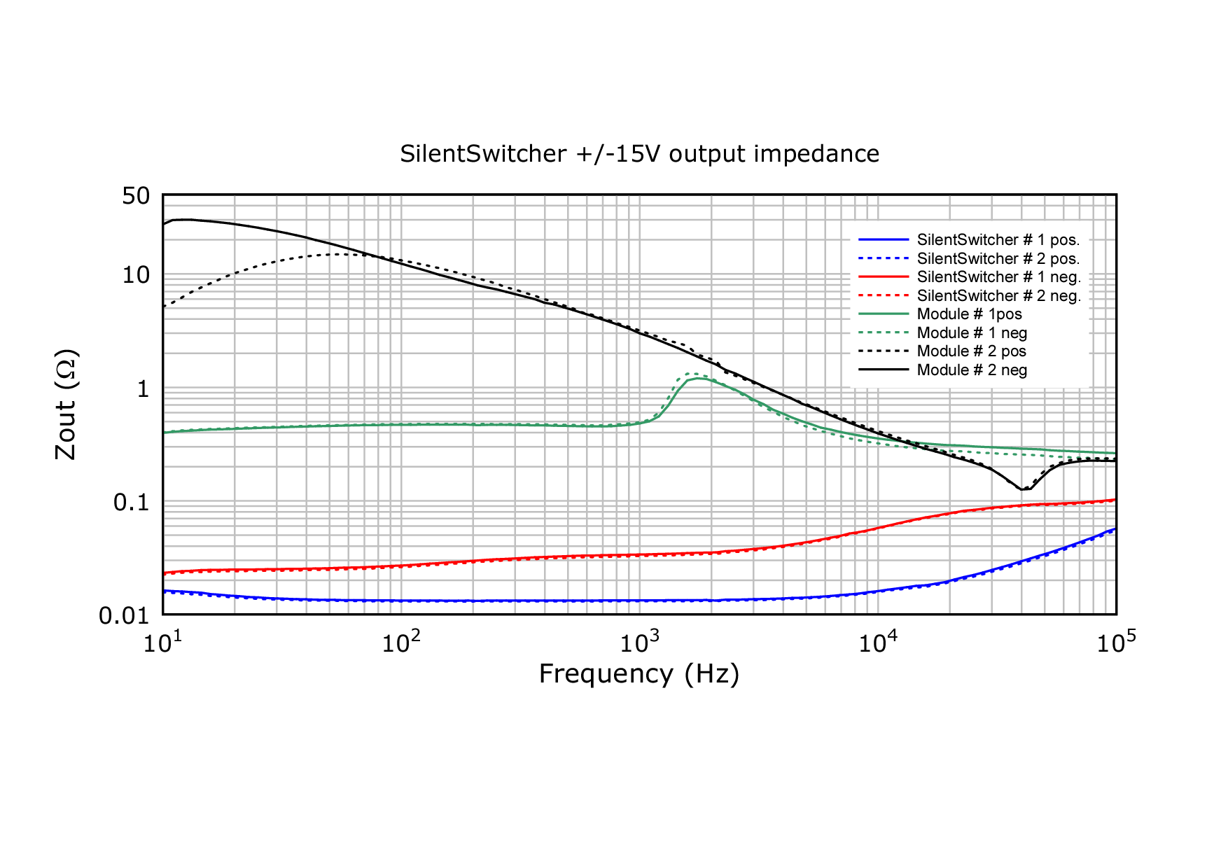
The impedance graph shows the output impedance of the SilentSwitcher, in comparison with a pair of commercially available similar modules. Again, nothing to be ashamed off!
The 'digital' (6/5/3.3V) output regulator has less than 5mV noise at 450mA. The output voltage drop resulting from a load current increase from 300mA to 450mA is just 3mV.
To clarify how it would work with the UB-B connector directly on the PCB, I shot the following pictures from the mech mock-up I made to verify dimensions and looks ;-).
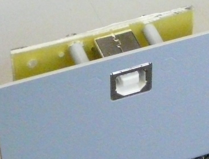
The USB connector is on the part side of the board; the parts and headers are at the same side as the USB connector and, when mounted on the enclosure panel with the USB connector through the panel, face the panel as shown.
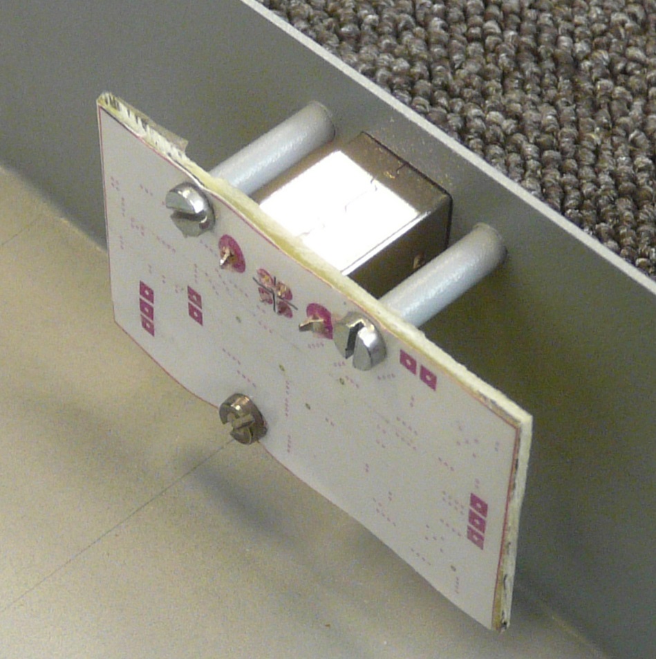
Then at the inside of the box you have access to all the power supply connections - +/-15V, and 6/5/3.3V as well as the connections for the On/Off switch.
That's all there is: that is the complete power supply. No wiring, no transformers, no mains hum and mains earth loops. You're done with it; now concentrate on the actual unit you are designing and building!