Update August 2021
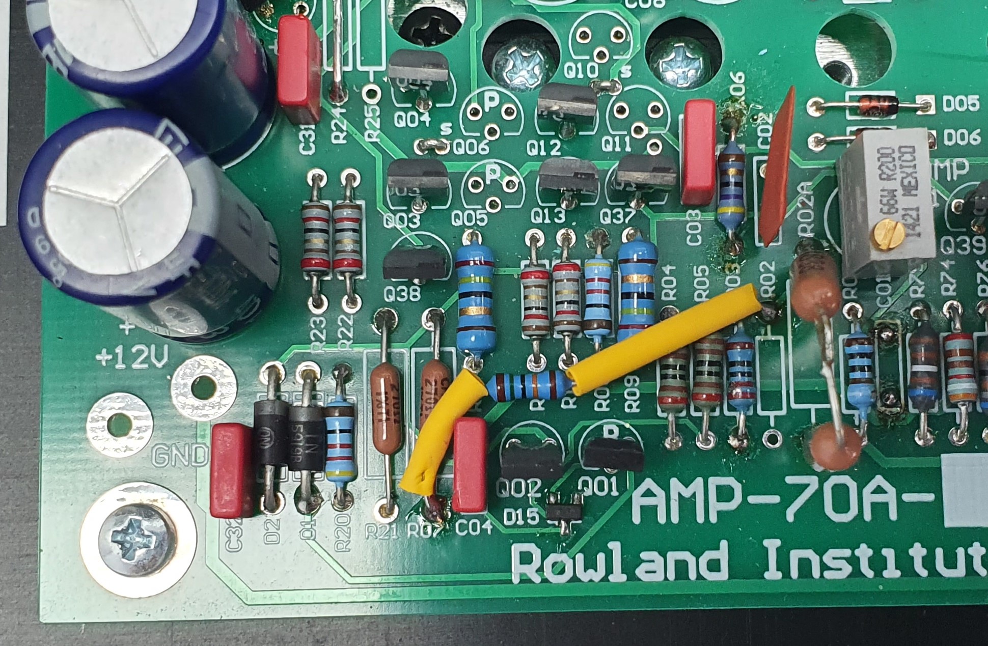
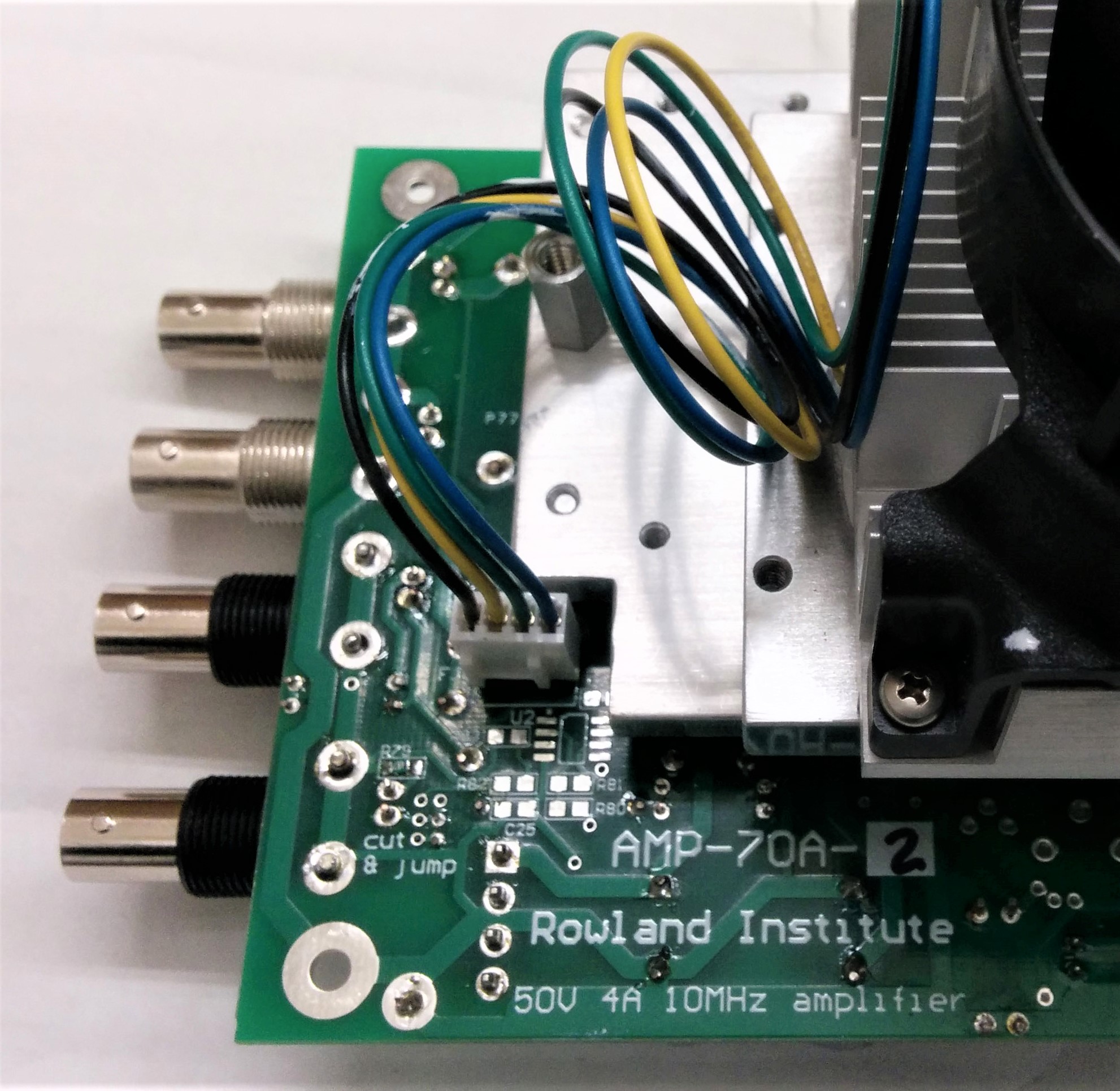
Finally got around to complete my two builds in a nice enclosure. I found that both had an output DC offset of some +1.2V. Short of adding a small DC servo, the best quick solution is adding an 180k resistor from the +15V supply to the input summing node, as shown in the pic. With this mod, the DC offset drops to about 50mV.
AMP-70 project
 This section is about the building of Winfield Hill's AMP-70 project. AMP-70 is a test and measurement amp, that looks innocent enough as a 100W audio power amp, but with a large signal bandwidth of minimum 5MHz! This amplifier has been designed by Winfield Hill (of Art of Electronics fame) for electromagnetic field experiments, but is also a great audio power amp. Some of us have also use for it driving power supply regulators with a combination of DC and AC to measure things like PSRR and Zout as a function of frequency. AMP-70's 5A, 50V ouput capability will cover pretty much all audio power supply regulators out there. Consider this as a build thread - I will expand and amplify the page as I and others progress in completing, testing and using this amplifier.
AMP-70 BOM AMP-70 - Circuit diagram AMP-70 input/driver stages - redrawn for clarity
Progress Report.
05 June 19 - Starting with the power supply subsystem. Mounted all supply caps, did the mod for the bipolar DC-DC converter (see List of known issues). Mounted all DC-DC converters. Tested all OK.
14 August 19 - Complete the first amp, up to and including a single output pair (Q21, 26). Running at +/-30V which is the maximum my current lab supply supports. Current consumption is 300mA which is nexactly what I calculated: 40mA each for the Q3.4 and Q12,13 chains; 80mA through the bias transistors Q20, 24; 60mA through the drivers Q19, 25; 80mA through the one output pair Q21, 26. There is an extra 350mA from the pos. supply for U1 DC/DC converter and downstream converters.
1kHz sine wave looks good, gain is ~10 x which is as expected: input opamp gain is 2, (R81/R80), main amp gain ~5, R02A/R01. But there is a ~6MHz low level (200mV pk-pk) oscillation visible at the output.
Modified the amp as follows to try tro cure it:
1. Connected the side of C01 that was connected to the output, to the emitter of Q25, as recommended by the German Tigris group;
2. Connected 33pF across the opamp feedback resistor R81, and connected the free end of R82 to gnd with a strap as foreseen;
3. Connected a zobel of 20 Ω and 0.1nF across the amplifier output;
4. Inserted a 10 Ω base stopper directly at the base pins of Q19, 25 (also recommended by Tigris);
5. Isolated the TO220 devices mounting plate from gnd, and let it float; and connected it to Vout through a resistor to 'bootstrap' the output devices tab capacitance;
None of these sequential changes had any impact on the 6MHz low level oscillation. Any hints welcome!